Industrial automation · Controls and motion
EtherCAT motion control and PLC programming for machines
We design and program the control layer of your machine: servo axes and drives, the PLC or motion controller, EtherCAT and other fieldbuses, and the operator interface. For new machines and retrofits of existing ones.
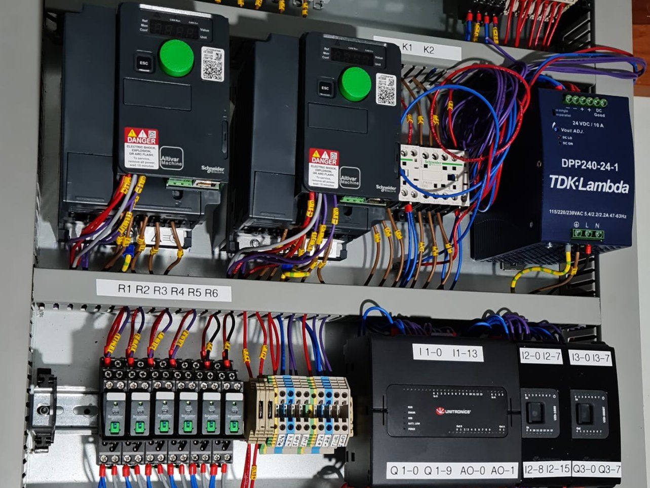
We work with Siemens, LS Electric, Unitronics and Controllino PLCs, and with EtherCAT, Modbus and CAN bus
- For
- Machine builders and plants that need a machine's control and motion layer designed, programmed or fixed
- You get
- Documented PLC code, electrical drawings, an HMI, and acceptance tests at the workshop and on site
- First step
- A call with an engineer about the machine, then an I/O list and a specification
Choosing a controller
PLC, motion controller or MCU: which fits the machine?
The general PLC-versus-microcontroller choice is covered on our industrial automation page. Here the question is motion: how many axes, how fast they move, and how tightly they need to be synchronised.
The choice comes down to three questions: how many axes the machine has, whether they move together along a shared path or each on its own, and what cycle time the line needs.
- A PLC with built-in motion control: fits most machines, from simple single-axis positioning to several synchronised axes. Standard PLCopen motion blocks are familiar to maintenance engineers, so your plant can look after the machine itself.
- A dedicated motion controller or an industrial PC as the EtherCAT master: when there are many axes, interpolation along a complex path, electronic gearing or cams, or a very short cycle time. It usually works alongside a PLC that handles the machine logic.
- A microcontroller on a custom board: when the motion is part of a product or a test rig rather than a production machine, and unit cost or size decides. Firmware and embedded software development
In every case the drives connect to the controller over a fieldbus, not with separate wiring per axis. EtherCAT suits motion particularly well: every axis is updated in the same cycle, and a shared clock keeps them in sync. CAN bus and Modbus suit simpler axes and instruments.
Controllers and comms
Which PLCs and fieldbuses do we work with?
These are the controllers and fieldbuses we work with in practice. LS Electric was formerly LSIS. A different controller or network? We review its documentation and the machine before we commit.
PLCs
- Siemens
- LS Electric
- Unitronics
- Controllino
Comms and fieldbuses
- EtherCAT
- Modbus
- CAN bus
- FDCAN
- RS-485
- RS-232
Programming, drives and HMI
- IEC 61131-3
- Ladder logic
- STEP 7
- VFD
- HMI
- Real-time Linux
Retrofits
Control retrofits for existing machines
When the machine itself is sound but the PLC is obsolete, parts are unavailable or there's no documentation, the control layer can be replaced and the mechanics kept. That's often the right step before buying a new machine.
A control retrofit starts with a backup and a survey, before anything is replaced:
- A backup of the existing PLC program and the drive parameters, if they can be read.
- A map of the inputs and outputs, wiring and motions, and redrawn electrical schematics where none exist.
- A list of what gets replaced and what stays: controller, drives and motors, sensors, operator interface.
- New software that first reproduces the existing behaviour, and only then adds improvements, so operators aren't caught out.
- Installation during a planned shutdown, with a rollback plan in case something doesn't work as expected.
When the machine needs a repair first, or it's unclear whether it's worth retrofitting, we start with a service visit and a diagnosis.
Process
How we work: from specification to commissioning on site
Six phases, each with a deliverable you approve. The software is tested against a simulation before it meets the machine, so there's less trial and error on the line. Each phase's duration is estimated after the initial evaluation.
01 · URS
Specification
What each axis does, how fast and how precisely, which operating modes there are, and what happens on a fault or an emergency stop. And what the operator needs to see and adjust.
Output: Functional specification and requirements
Gate: You approve the specification
02 · I/O
I/O list and architecture
A list of every sensor, actuator and axis; the choice of controller, drives and fieldbus; and the control-panel design.
Output: I/O list, control architecture and electrical schematics
Gate: A joint design review before components are ordered
03
Programming
The PLC program to IEC 61131-3: motion blocks, manual and automatic modes, fault handling and alarms, and the operator interface.
Output: PLC and HMI software, with code comments and version control
04 · HIL
Simulation and HIL tests
We run the software against a simulation of the machine, or a HIL rig with real drives, and test scenarios and faults before reaching the line.
Output: Test results for every scenario in the specification
Gate: The software passes the test scenarios
05 · FAT
Factory acceptance test
We test the control panel and the software with the machine, or part of it, against a protocol you approved in advance.
Output: FAT protocol and results
Gate: The system passes the FAT
06 · SAT
Commissioning and SAT
Start-up at your plant, axis tuning, the site acceptance test and training for operators and maintenance. The software is handed over as a documented release.
Output: SAT results, documented software and training
Gate: You sign off on the system
From our projects
What does this look like on a real project?
Full automation for a building-products plant
Controls and motion control, frequency drives and sensors, from control-panel design to on-site commissioning.
Motion control and PLC programming: FAQ
What drives the cost of a controls and motion project?
The number of axes and how tightly they're synchronised, the I/O count, the scope of the operator interface, and whether it's a new machine or a retrofit of an undocumented one. That's why the cost is set in a written proposal, after the specification and the I/O list.
For a retrofit we sometimes start with a survey and backup phase, so the proposal is based on what's actually in the machine rather than on a guess.
Can you replace an old PLC that's no longer supported?
Yes. When the old controller is no longer sold or has no spares, we replace it with a current one, and usually keep the mechanics, the motors and sometimes the drives. We start by backing up the existing program, if it can be read, and mapping the wiring. If the program is locked or lost, we rewrite it from what the machine actually does, with help from the operators who know it.
Do we get the PLC source code?
Ownership of the source code and files is agreed in the contract for each project. Either way, the software is handed over with code comments, an I/O list, electrical schematics and an operator and maintenance guide, so your maintenance team or another engineer can keep working on it.
Do you design the operator interface too?
Yes. The HMI is designed together with the PLC program: production screens, a manual mode for setup and maintenance, alarms that explain the cause and not just the code, and a recipe screen when there are several product variants. We build the screens with your operators, so routine faults can be handled without waiting for an engineer.
How is the PLC program tested before it reaches the machine?
Against a simulation. The program runs against a model of the machine, or a HIL rig wired to the real controller and drives, through the scenarios in the specification, including faults and stops. That way most bugs can be found at the workshop, and less time goes on trials on the line.
Tell us what the machine needs to do, or what isn't working today
Describe the axes, the controller, the fieldbus and what's in the way. An I/O list or electrical drawings, if you have them, help. An engineer will reply with questions and a next step.
Usually a reply within 3 working hours, by email or phone